Choosing the right Flame Arrestor For Tanks is not a decorative upgrade. It is a carefully engineered barrier between stored vapors and a possible ignition source. A poor choice may restrict breathing, increase pressure loss, or fail under the wrong flame condition. The tank’s product, vapor concentration, operating temperature, pressure, and connection size all matter. So does the installation location.
Trevor Kletz, a pioneer in process safety, warned, “If you think safety is expensive, try an accident.” His message still fits tank protection. A flame arrestor must match the hazard, not merely the pipe diameter. The seven tips in this guide examine deflagration and detonation risks, end-of-line and in-line designs, flame velocity, pressure drop, temperature limits, maintenance access, and verified performance data. Small details matter. A blocked element can quietly change the entire protection strategy.
Real facilities are rarely perfect. Dust gathers. Inspection schedules slip. Product temperatures vary more than expected. These conditions deserve honest attention. Selecting equipment from a reputable manufacturer is important, but it is not enough. Engineers should review test certificates, installation drawings, material compatibility, cleaning procedures, and replacement requirements. Independent technical review can expose assumptions before commissioning. Sometimes, the first selection looks correct on paper and still needs revision. That is not failure. It is responsible engineering. This article offers practical guidance for making a safer, more defensible choice for tank storage systems.
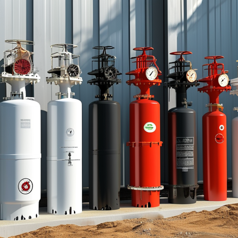
A tank’s operating conditions should guide flame-arrestor selection, not the product name or connection size. Record normal and maximum temperature, pressure, vapor flow, liquid level, filling rate, and emptying rate. API Standard 2000 emphasizes evaluating normal and emergency venting demand under realistic operating scenarios. A tank filled in winter may behave differently during summer loading.
The hazard profile needs equal attention. Identify the stored liquid’s flash point, vapor pressure, autoignition temperature, and vapor group. Under OSHA’s classification, a flammable liquid can have a flash point below 93°C. That threshold is significant. Vapors may ignite even when the liquid appears calm. NFPA 30 guidance also supports reviewing liquid classification, storage temperature, and ignition sources before choosing protection. Do not rely on a safety data sheet alone; process data can expose operating conditions that the sheet does not cover.
Specify whether deflagration protection is needed on the vent, inlet, outlet, or both. Check the vapor’s maximum experimental safe gap, expected flow velocity, and pressure-drop limit against the arrester’s certified performance. API 2000 and recognized testing practices stress capacity, endurance, and installation orientation. A smaller device may reduce cost but restrict breathing. That mistake is easy to make. Recheck the calculation after changing tank volume, liquid composition, or loading speed. Real facilities evolve, while old specifications quietly remain.

7 Tips to Choose the Best Flame Arrestor for Tanks?
Match the Flame Arrestor to the Required Protection Type
Selecting a flame arrestor starts with the hazard, not the tank diameter. API Standard 2000 separates normal venting from emergency venting and fire exposure. These duties require different airflow and pressure calculations. A device for atmospheric breathing may not protect against flame transmission through a process line. Check the expected vapor composition, operating temperature, pressure, and flow rate. Methanol vapor behaves differently from hydrocarbon vapor. Small details matter.
For deflagration protection, review test evidence under ISO 16852. The report should identify flame speed, gas concentration, temperature, and installation distance. Detonation protection requires a different design basis. Do not assume one arrestor covers both conditions. NFPA 69 also emphasizes explosion prevention through isolation, suppression, and controlled system design. Confirm the required pressure rating and maintenance interval. A clogged element can restrict venting before an incident occurs. That risk is easy to underestimate.
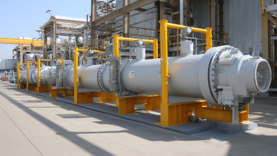
Tank location changes the selection. End-of-line units protect atmospheric openings, while in-line units protect connected piping. Fire exposure may require a liquid seal, emergency vent, or separate isolation system. Verify the arrestor’s tested orientation and allowable pressure drop. Published test data is more valuable than a generic catalog claim. I would also challenge the first selection after reviewing seasonal temperature changes and cleaning records. Field conditions are rarely perfect.
7 Tips to Choose the Best Flame Arrestor for Tanks
Evaluate Gas Flow, Pressure, Temperature, and Pipe Size
Selecting a flame arrestor starts with the gas, not the tank connection. Identify the normal flow rate, peak flow, gas composition, and operating pressure. Vapor conditions can change during filling, emptying, or thermal expansion. A device with excessive pressure loss may restrict breathing and affect tank performance. A device with insufficient capacity may fail to control flame propagation effectively.
Check the pipe’s inside diameter, not only its nominal size. Reducers, elbows, valves, and long pipe runs can change flow behavior. Compare the arrestor’s published pressure-drop data with actual operating conditions. Confirm whether the installation needs deflagration or detonation protection. The answer depends on flame path length and piping layout. Field measurements matter here. Assumptions can be wrong.
Temperature requires equal attention. Select materials and certified operating limits that cover normal service, cleaning, and possible process upsets. Also verify the pressure rating against both working and emergency conditions. Keep the arrestor accessible for inspection and cleaning. Dust, condensation, and polymer deposits can block passages. A tidy calculation is not enough. Review the selection with process, mechanical, and safety personnel before purchase. The first sizing pass is rarely perfect.
| Tip | Key Evaluation Dimension | Realistic Data or Example | What to Check | Selection Guidance |
|---|---|---|---|---|
| 1. Identify the Flame Event | Flame propagation type | Deflagration flames typically propagate below the local speed of sound, while detonation involves a shock wave and much higher flame-propagation severity. | Determine whether the arrestor is installed on a tank vent, an open-ended vent line, or a pipe where ignition can occur away from the tank. | Use a device specifically tested and certified for the expected event. A deflagration-only arrestor should not be treated as a detonation arrestor. |
| 2. Match the Gas or Vapor | Gas composition and explosion properties | Common flammable gases and vapors have different maximum experimental safe gaps, laminar flame speeds, flash points, and autoignition temperatures. Hydrogen, for example, requires more stringent consideration than many hydrocarbon vapors. | Confirm the gas name, concentration range, oxygen availability, maximum experimental safe gap or equivalent classification, and whether the composition can change during operation. | Select an arrestor tested for the actual gas group or vapor classification. Do not select solely by nominal pipe diameter. |
| 3. Calculate Gas Flow | Normal and maximum flow rate | Example screening case: a tank vent may require 1,200 Nm³/h during filling and 800 Nm³/h during thermal breathing. The arrestor should be checked at the maximum credible flow, not only the average flow. | Include filling, emptying, vapor recovery, emergency venting, thermal expansion, and pressure-vacuum valve interaction. Convert standard flow to actual operating conditions before checking velocity and pressure loss. | Choose an arrestor whose certified flow capacity exceeds the required operating flow while maintaining acceptable pressure drop and stable tank pressure. |
| 4. Check Pressure Drop | Allowable pressure loss | Low-pressure storage tanks may operate only a few millibars above atmospheric pressure. Even a moderate arrestor pressure drop can affect venting performance and tank protection. | Compare the arrestor pressure drop at minimum, normal, and maximum flow with the tank design pressure, vent valve settings, and total line pressure loss. | Prefer a larger flow area or a lower-pressure-drop design when the tank has a narrow operating pressure window. Use the manufacturer’s certified pressure-drop curve. |
| 5. Verify Temperature Limits | Operating, ambient, and ignition temperature | Example operating envelope: −20°C to +60°C. The arrestor materials and element rating must also tolerate the vapor temperature and the heat generated during a flame event. | Check normal process temperature, minimum ambient temperature, maximum ambient temperature, solar heating, steam cleaning, condensation, and the gas or vapor autoignition temperature. | Select materials, gaskets, and a certified temperature class suitable for the complete operating envelope. Prevent ice, hydrate, or condensate blockage in cold service. |
| 6. Confirm Pipe Size and Installation | Nominal pipe size, connection, and layout | A 4-inch nominal line does not automatically require a 4-inch arrestor if reducers, valves, elbows, or a different connection standard are present. Line size must be considered together with flow area and system pressure loss. | Verify nominal diameter, flange or threaded connection, pressure rating, face-to-face dimensions, flow direction, upstream and downstream straight lengths, and accessibility for inspection. | Match the arrestor connection to the piping system and avoid unnecessary reducers. Follow the certified installation orientation and distance limits. |
| 7. Plan Maintenance and Certification | Inspection, fouling, and compliance | Dust, polymerizing vapors, corrosion products, and condensate can obstruct the flame-quenching element and increase pressure drop. Inspection intervals should be risk-based and established before commissioning. | Check drain arrangements, access for element removal, differential-pressure monitoring, corrosion allowance, replacement parts, test certificates, and applicable requirements such as ISO 16852 or equivalent local regulations. | Choose a design that can be inspected and cleaned without compromising the flame-arresting element. Record pressure-drop trends and replace damaged or excessively fouled components. |
Tip 1: Match the arrestor material to the tank contents and environment. Stainless steel suits corrosive vapors, while coated carbon steel may fit milder service. Check temperature, pressure, and chemical compatibility, not only purchase price.
Tip 2: Confirm the device is certified for the actual vapor mixture. Review its gas group, temperature class, pressure rating, and tested direction of flame protection. Certification must match the installation, not just the product category. Ask for traceable test documents. Do not rely on a familiar logo or verbal assurance.
Tip 3: Select the correct connection size and flow capacity. A restriction can increase tank pressure or reduce venting performance.
Tip 4: Check whether the arrestor supports horizontal or vertical installation. Field experience shows that orientation errors are surprisingly common.
Tip 5: Plan maintenance before installation. Dust, polymer deposits, and corrosion can block the flame path. Choose a design with accessible inspection covers and replaceable elements.
Tip 6: Follow the manufacturer’s cleaning limits and use approved tools. Aggressive scraping may damage small passages. Keep records of inspections, cleaning dates, and findings.
Tip 7: Review the complete installation with a qualified engineer. Include bonding, drainage, gaskets, supports, and nearby ignition sources. Poor alignment can strain the housing and leak over time. The best choice may still fail when installed carelessly. Recheck assumptions against site drawings and current local requirements.
Choosing the best flame arrestor for a tank requires more than comparing purchase prices. Compare pressure drop at the tank’s actual vapor flow, not only the catalog’s ideal rating. Ask for verified performance data from controlled testing. Confirm compatibility with vapor composition, operating temperature, pressure, and expected flow changes. Small details matter.
Review the element’s service life under real site conditions. Corrosive vapors, dust, condensation, and sticky deposits can shorten maintenance intervals. Check whether the housing and internal parts resist the stored product and cleaning process. Inspect access points before installation. A device that is difficult to open may increase labor costs and extend downtime. Keep records.
Calculate total ownership costs over several years. Include inspection labor, cleaning, replacement elements, energy loss from pressure drop, and production interruptions. A low-cost unit may become expensive after repeated shutdowns. Compare maintenance instructions, spare-part availability, test documentation, and technical support from qualified professionals. Use applicable engineering standards and a site-specific risk assessment.
Field reviews often reveal a practical weakness: the selected model fits the drawing but not the maintenance routine. A unit may perform well in testing yet struggle with seasonal condensation. Recheck assumptions after commissioning. Measure pressure drop, inspect deposits, and revise the service schedule when operating data disagrees with the original plan.
Compare pressure-drop performance, expected service life, and estimated 10-year ownership cost.
Representative engineering values for clean, correctly sized equipment: lower pressure drop improves tank breathing efficiency, while longer service life and lower ownership cost support better lifecycle value. Actual results vary with gas composition, flow rate, temperature, corrosion, inspection frequency, and applicable standards.