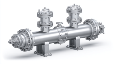
Selecting an Emergency Relief Valve is a safety decision, not a routine purchasing task. The wrong set pressure, material, or discharge arrangement can turn a manageable overpressure event into equipment damage, production loss, or injury. API 520 and API 521 remain key references for sizing, installation, reaction forces, disposal systems, and relieving scenarios. They also remind engineers that valve selection cannot be separated from the entire pressure-relief system.
Industry investigation reports from the U.S. Chemical Safety and Hazard Investigation Board repeatedly show a similar weakness: safety systems may exist, but poor design assumptions, blocked discharge paths, or inadequate maintenance reduce their protection. That detail matters. A valve may look correct on a datasheet while failing in a cold, vibrating, corrosive plant environment. Process-safety expert Trevor Kletz offered a lasting warning: “If you think safety is expensive, try ignorance.” His point applies directly here.
This guide presents seven practical tips for choosing an Emergency Relief Valve. It considers pressure data, temperature changes, fluid behavior, materials, certification, installation, and inspection access. Field experience suggests that small details matter, such as a fouled inlet screen, a mismatched gasket, or an unnoticed backpressure increase. No selection method is perfect. Operating conditions change, and design margins can be misunderstood. That is why engineers should verify calculations with qualified specialists, current standards, manufacturer data, and real maintenance records before approval.

Tip 1: Define the pressure conditions before selecting an emergency relief valve. Identify the normal operating pressure, maximum allowable working pressure, and credible emergency pressure. Include blocked outlets, external fire, thermal expansion, and control failure. Each scenario may create a different relieving load.
In field reviews, pressure data is often incomplete. That is a problem. Confirm the pressure source, expected accumulation, and valve inlet losses. Check built-up and superimposed backpressure, especially when the discharge line connects to a closed system. A valve can appear correctly sized yet perform poorly under actual backpressure. Use applicable engineering standards and verified process calculations.
Tip 2: Establish the full temperature range, not only the normal operating temperature. Record the relieving temperature, startup temperature, shutdown temperature, and possible fire exposure. Temperature changes can alter fluid density, vapor generation, viscosity, and material strength. For liquids, thermal expansion may control the required relief capacity. For gases, temperature strongly affects flow calculations.
Tip 3: Match the valve materials and seals to the coldest and hottest conditions. A seal that works at 20°C may become brittle during a cold depressurization event. A body material may lose strength at elevated temperature. I have seen specifications focus heavily on pressure while treating temperature as a secondary detail. That approach needs reconsideration. Verify every assumption against process records, operating history, and realistic emergency scenarios.
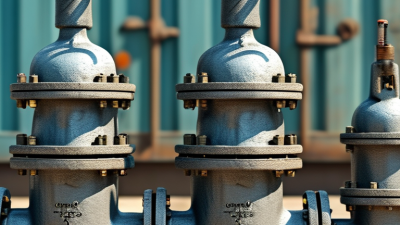
An emergency relief valve must match the equipment, not merely the connection size. Start by identifying the protected vessel, pipe section, or thermal circuit. Then confirm pressure, temperature, fluid phase, and required relieving capacity. The National Board of Boiler and Pressure Vessel Inspectors’ incident reporting links recurring pressure events with overpressure, corrosion, and blocked discharge paths. These findings make application details essential.
For steam or gas service, a spring-loaded safety valve may provide rapid pressure release. Liquid service usually needs a relief valve designed for liquid flow. A pilot-operated valve can suit large systems, but contamination and unstable pressure require careful review.
Check the set pressure against the equipment’s maximum allowable working pressure. Confirm backpressure, discharge routing, and material compatibility. Small errors matter.
I have seen valves selected from pipe size alone. That is risky. The valve must pass the required flow under real relieving conditions. API 520 Part I provides sizing methods, while API 521 addresses disposal systems and credible overpressure scenarios. Review blocked outlets, fire exposure, control-valve failure, and thermal expansion. Also inspect the inlet line for pressure loss and vibration. A field test can reveal problems that calculations miss. I still recheck assumptions after commissioning. Real systems behave imperfectly. Record the final set pressure, test date, and operating conditions for future maintenance.
7 Tips for Choosing an Emergency Relief Valve
Verify Sizing, Capacity, and Pressure-Setting Requirements
Relief valve selection begins with the credible overpressure scenario. Define blocked outlets, thermal expansion, fire exposure, gas blowdown, and control failure. Do not start with the pipe size. Start with the required relieving case.
API 520 Part I uses relieving pressure, temperature, compressibility, and flow capacity for valve sizing. API 521 also calculates fire exposure from wetted surface area, not vessel volume alone. Check the manufacturer’s certified coefficient, then compare it with the required mass flow. Account for inlet pressure loss and built-up backpressure. A spreadsheet can still lie.
Pressure setting must protect the equipment’s maximum allowable working pressure. ASME BPVC Section VIII commonly permits 10% accumulation for many single-device cases. Fire cases may allow 21%, depending on the design and jurisdiction. These numbers are not universal. Confirm the governing code.
I have seen valves selected correctly on paper but poorly installed. Verify discharge piping, reaction forces, drainage, and access for testing. Record set pressure, cold differential test pressure, operating pressure, and temperature. Keep the normal operating pressure comfortably below the set point. API 576 inspection guidance supports documented testing and condition monitoring. Test intervals should reflect service severity, leakage history, and process risk. Process conditions change. Review the calculation after equipment modifications, not only after an incident.
Verify sizing, capacity, and pressure-setting requirements before selecting an emergency relief valve. The chart shows commonly referenced allowable overpressure values for pressure-relief scenarios under ASME Section VIII, Division 1. Always confirm the governing code, design case, and system documentation.
Choosing an emergency relief valve starts with the material, not the catalog image. Tip 1: Match the valve body to the process fluid. Stainless steel may resist moisture, while corrosive chemicals can require higher-grade alloys. Tip 2: Check seal materials carefully. Heat, solvents, and repeated pressure changes can harden or swell unsuitable seals. Tip 3: Confirm pressure and temperature ratings from verified technical documents. A valve that fits the pipe may still fail under real conditions.
Compatibility needs practical checking. Tip 4: Compare the valve connection with the existing piping, including thread type, flange dimensions, and gasket material. Small mismatches create leaks. Tip 5: Review the fluid’s density, viscosity, and possible contamination. Thick liquids or particles may prevent reliable opening. In field inspections, I have seen clean-looking lines hide buildup near the relief path. That detail is easy to miss.
The operating environment also changes the selection. Tip 6: Consider vibration, outdoor exposure, dust, and washdown routines. Tip 7: Allow for temperature swings during startup and shutdown. A cold morning can affect seals differently from a hot production cycle. Check access for testing and maintenance. It matters. One honest weakness is assuming normal operation tells the whole story. Emergency valves must respond during abnormal conditions, so review blocked outlets, sudden pressure spikes, and nearby equipment before approval.
| No. | Selection Tip | What to Check | Practical Guidance | Common Risk | Acceptance Indicator |
|---|---|---|---|---|---|
| 1 | Define the relieving scenario | Identify blocked outlet, fire exposure, thermal expansion, utility failure, runaway reaction, or gas blow-by. | Calculate the required relief load for the governing scenario rather than selecting a valve only by pipe size. | An undersized valve may not prevent overpressure; an oversized valve may chatter or lose stable operation. | Documented relief case and verified required capacity. |
| 2 | Match set pressure to the protected equipment | Check the equipment design pressure, allowable accumulated pressure, operating pressure, and applicable code requirements. | Set pressure must protect the weakest pressure boundary and should allow sufficient margin above normal operating pressure to avoid nuisance lifting. | Frequent lifting, seat damage, leakage, or pressure exceeding the equipment rating. | Set pressure and accumulation comply with the governing design code. |
| 3 | Choose compatible body and trim materials | Evaluate fluid chemistry, concentration, temperature, moisture, chlorides, hydrogen exposure, erosion, and corrosion potential. | Common material options include carbon steel for suitable non-corrosive services, stainless steel for many corrosive or hygienic services, and nickel-based alloys for more severe chemical environments. | Corrosion, stress-corrosion cracking, galling, embrittlement, or loss of sealing performance. | Material certificates and documented compatibility review are available. |
| 4 | Confirm the operating temperature range | Review normal, minimum, maximum, relieving, start-up, shutdown, and transient temperatures. | Consider loss of spring strength, brittle fracture at low temperature, thermal expansion, gasket limits, and changes in fluid density or viscosity. | Valve sticking, leakage, incorrect capacity, or failure of soft components. | All wetted and non-wetted components are rated for the full temperature envelope. |
| 5 | Check fluid phase and required capacity | Determine whether the valve will relieve gas, steam, liquid, vapor-liquid mixture, or a flashing fluid. | Use the correct sizing method and account for molecular weight, compressibility, viscosity, vapor pressure, backpressure, and two-phase flow where applicable. | Incorrect sizing can cause insufficient flow capacity, unstable operation, or excessive reaction forces. | Capacity is certified for the actual relieving fluid and conditions. |
| 6 | Evaluate backpressure and discharge piping | Check built-up and superimposed backpressure, outlet pipe length, fittings, drains, supports, and discharge destination. | Select conventional, balanced-bellows, or pilot-operated construction when service conditions require control of backpressure effects. | Reduced capacity, unstable popping, premature opening, or discharge-line vibration. | Piping pressure losses and reaction forces remain within design limits. |
| 7 | Consider the complete operating environment | Review outdoor exposure, vibration, dust, salt spray, hazardous areas, accessibility, maintenance intervals, and inspection requirements. | Provide suitable weather protection, corrosion protection, lifting access, isolation controls, drainage, and safe discharge routing without compromising valve function. | Blocked outlets, frozen components, difficult testing, unsafe discharge, or delayed maintenance. | Installation, testing, access, and discharge arrangements are approved by safety and engineering personnel. |
Review certification before comparing price. Ask for current certificates, material records, pressure-test results, and traceable serial numbers. Confirm that the valve’s set pressure matches the protected equipment. A certificate alone is not proof of suitability. Check the issuing body, testing date, and applicable pressure standards. If documents look incomplete, pause the purchase.
Choose a design with accessible inspection points and replaceable sealing parts. Ask how often testing is recommended under your operating conditions. Dust, corrosion, vibration, and temperature changes can shorten service intervals. Keep clear records of every inspection. Small leaks often become expensive warnings. I have learned that “maintenance-free” rarely means attention-free.
Request response times, spare-part availability, technical drawings, and service instructions. A dependable supplier should explain limitations without hiding behind technical language. Ask whether technicians can review installation conditions remotely or on site.
Even a correctly selected valve can perform poorly after careless installation. Confirm who handles retesting, adjustment, and documentation. Do not rely on verbal promises. Put critical support details in writing.
Review the supplier’s experience with similar media, temperatures, and pressure cycles. References from comparable facilities can reveal practical weaknesses. Product selection is not perfect science. Recheck assumptions when process conditions change.