What Is a Vacuum Relief Valve and How Does It Work?
A Vacuum Relief Valve protects tanks, vessels, and piping from excessive negative pressure. It opens when internal pressure falls below a preset vacuum level. This allows clean air or another approved gas to enter the system. Without that relief path, atmospheric pressure can deform a storage tank, collapse a wall, or damage connected equipment.
In practical service, the valve may sit on a tank roof, beside a breather, or within a process line. A spring-loaded disc, weight, or pilot mechanism normally keeps the opening closed. When liquid leaves quickly, vapor condenses, or the tank cools, internal pressure drops. The valve then responds to the pressure difference, not to the visible movement of the liquid. That detail is easy to overlook.
A reliable Vacuum Relief Valve must match the vessel’s capacity, operating temperature, fluid, and required airflow. Engineers also check set pressure, materials, connection size, and possible contamination. Routine inspections can reveal sticking discs, blocked vents, damaged seals, or corrosion around the seat. Small defects matter.
It should not be treated as a universal substitute for pressure protection. Many systems need separate pressure relief equipment for overpressure conditions. Manufacturer data, engineering calculations, and applicable industry standards should guide selection and installation. Field experience helps, but it is not enough alone. Even a well-designed valve can fail if maintenance is neglected or the vent path is restricted.
The following discussion explains how this device works, where it is used, and what should be reviewed before installation. Some applications remain more complex than a short explanation suggests. That uncertainty deserves attention.
Definition and Purpose of a Vacuum Relief Valve
What Is a Vacuum Relief Valve and How Does It Work?
A vacuum relief valve is a protective device that prevents excessive negative pressure inside a tank, vessel, or pipeline. It opens when internal pressure falls below a preset vacuum level. Air or another approved gas then enters the system. This action balances pressure and reduces the risk of structural damage.
Vacuum can develop during tank draining, product cooling, condensation, or sudden line blockage. Without protection, a storage tank may deform inward, like a thin metal can under pressure. The valve usually contains a spring-loaded disc, weighted mechanism, or diaphragm. Under normal conditions, the sealing element remains closed. When the vacuum reaches its set point, atmospheric pressure moves the element open.
The valve is not the same as a pressure relief valve. A pressure relief valve releases excess internal pressure, while a vacuum relief valve admits air during underpressure. Some systems require both functions. Selection depends on vessel strength, flow rate, temperature, fluid properties, and the acceptable pressure range.
Correct sizing matters. A valve that opens too late may not protect the vessel. A valve that opens too easily may cause unwanted air entry or contamination. The exact setting is easy to underestimate. Engineers should review operating data, inspection records, and credible design standards before installation. Maintenance staff also need to check the seat, spring, vent path, and signs of corrosion. Small obstructions can change performance.
Main Components and Their Functions
What Is a Vacuum Relief Valve and How Does It Work?
A vacuum relief valve protects tanks, vessels, and pipelines from excessive internal vacuum. It opens when outside pressure becomes greater than the pressure inside the equipment. Air or another approved gas then enters through the valve. This action helps prevent tank walls from bending, buckling, or collapsing during draining, cooling, or sudden condensation.
Main Components and Their Functions
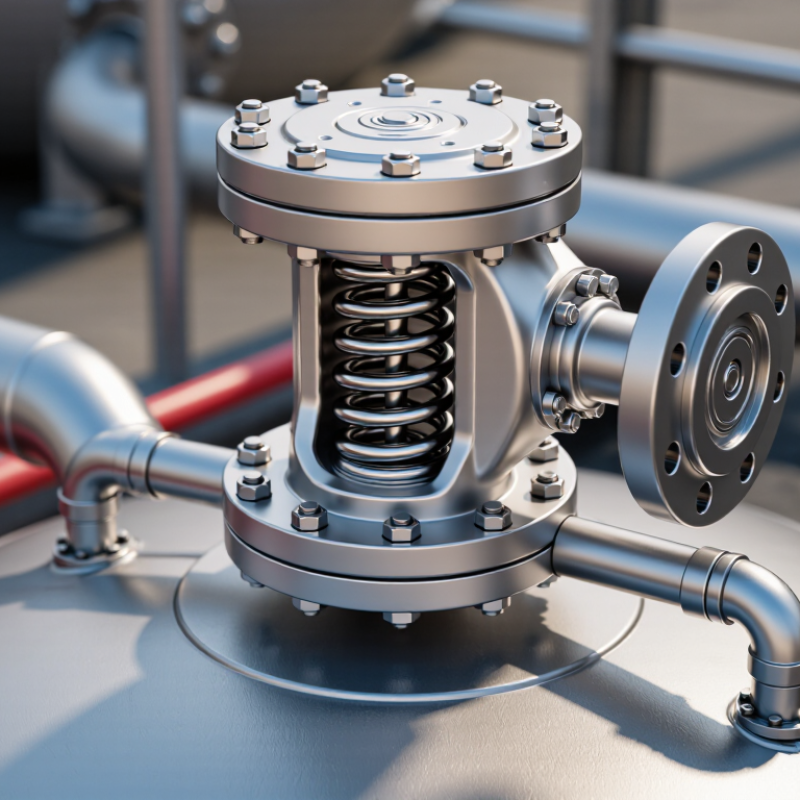
The valve body forms the pressure boundary and connects to the vessel nozzle. Inside, the valve seat provides the sealing surface. A disc or poppet rests against this seat when the valve remains closed. Its movement controls the inlet flow. A spring, weight, or calibrated actuator supplies the closing force and determines the vacuum set point. The guide keeps the disc aligned during opening and closing. Gaskets reduce leakage around joints, while the cover protects internal parts from dust and weather. Some designs include a screen to limit debris entry.
The design looks simple. Inspection is not. During routine maintenance, technicians should check the seat, disc, guide, and spring for corrosion, deposits, or sticking. Even a small particle can prevent proper sealing. A set point suitable for an empty tank may not suit a heated process. Temperature, flow rate, vessel strength, and gas compatibility require careful review. I would also question any valve that opens repeatedly without a clear process change. The valve may be protecting the equipment, or it may be revealing a deeper operating problem.
What Is a Vacuum Relief Valve and How Does It Work?
A vacuum relief valve admits air when vessel pressure falls below its set point. The chart uses absolute pressure values from a representative low-pressure vessel example; atmospheric pressure at sea level is 101.3 kPa absolute.
Valve Body
Contains the flow passage and connects the valve to the protected vessel.
Seat and Disc
Seal the opening during normal operation and lift when vacuum reaches the set point.
Spring or Weight
Provides the closing force that determines the valve’s opening pressure.
Guide and Cap
Keeps moving parts aligned and helps protect the mechanism from contamination.
How a Vacuum Relief Valve Works Step by Step
A vacuum relief valve protects a tank when internal pressure falls below its safe operating limit. According to API Standard 2000, atmospheric and low-pressure storage tanks may operate from vacuum conditions up to 15 psig. The valve must match the tank’s design pressure, venting demand, and stored liquid.
The process begins when liquid leaves the tank, or when hot vapor condenses after cooling. Internal pressure then drops. A sensing element detects this pressure difference. When the vacuum reaches the valve’s set point, atmospheric pressure pushes the pallet or diaphragm open. Air enters through the valve opening and reduces the pressure difference. The valve closes after pressure returns within its operating range.
It sounds simple.
ISO 28300 emphasizes calculating normal inbreathing, outbreathing, and emergency venting separately. Field technicians should also check valve capacity, temperature, corrosion, and fouling. A dirty seat may prevent tight closure. A weak spring may change the set point. These details matter during routine inspection.
API 2000 does not support one universal valve size or setting. Engineers must use tank geometry, filling and emptying rates, vapor properties, and credible thermal cases. In practice, installation errors can be as serious as poor calculations. The inlet should remain unobstructed, and discharge piping should not create excessive backpressure. One assumption can fail: a valve that works on a clean test bench may perform differently after months of dust, condensation, or product vapor exposure.
Common Types and Typical Applications
What Is a Vacuum Relief Valve and How Does It Work?
A vacuum relief valve protects a tank when internal pressure falls below safe limits. This condition can occur during pump-out, rapid cooling, or liquid withdrawal. The valve opens inward, allowing air or inert gas to enter. Once pressure returns to the set point, the seating element closes. Simple in principle. Poor sizing can still deform a tank.
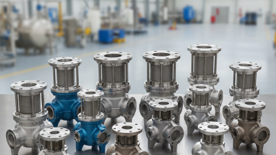
Common types include weighted pallet valves, spring-loaded valves, and pilot-operated designs. Weighted pallets suit many atmospheric storage tanks because they offer simple inspection and maintenance. Spring-loaded valves respond quickly and fit tighter pressure settings. Pilot-operated valves support larger capacities and more precise control, though contaminated gas can affect performance. Combination pressure-vacuum valves handle both overpressure and vacuum conditions. API Standard 2000 identifies liquid movement, thermal breathing, fire exposure, and emergency scenarios as key sizing considerations.
Typical applications include petroleum and chemical storage tanks, water-treatment vessels, food-processing systems, pharmaceutical equipment, and bulk silos. The U.S. Environmental Protection Agency’s AP-42 guidance separates tank breathing losses from working losses, showing why operating cycles matter. The U.S. Energy Information Administration has reported roughly 4 trillion cubic feet of working gas storage capacity in the United States, illustrating the scale of pressure-sensitive storage infrastructure. In the field, technicians still encounter valves selected from pressure alone. That approach is incomplete. Fluid properties, temperature changes, vent-line resistance, and maintenance access deserve equal attention.