Choosing the best Varec Pressure Vacuum Relief Valve is rarely a simple matter of comparing product names. The right choice depends on tank design, operating pressure, vapor characteristics, temperature, and maintenance conditions. A valve that performs well on a low-pressure storage tank may not suit a vessel handling volatile liquids. Small differences matter.
This guide examines practical selection factors, including pressure and vacuum settings, flow capacity, materials, connection sizes, and sealing performance. It also considers how the valve behaves during filling, emptying, thermal expansion, and sudden weather changes. In the field, technicians often notice the details first: a sticking pallet, a damaged gasket, or residue around the vent outlet. These signs can reveal problems before they become costly failures.
Performance data should come from manufacturer documentation, application calculations, inspection records, and qualified engineering review. Varec equipment has a strong reputation in tank protection, but reputation alone should not determine the purchase. Every installation has its own risks and limitations. There is no universal best valve.
That is worth remembering.
A reliable evaluation should compare the Varec Pressure Vacuum Relief Valve with the tank’s actual operating profile, not an idealized specification sheet. This article will help readers ask better questions, identify overlooked requirements, and balance safety, durability, maintenance access, and total ownership cost. Some recommendations may remain conditional. That is appropriate, because responsible valve selection begins with accurate site information, not confident assumptions.
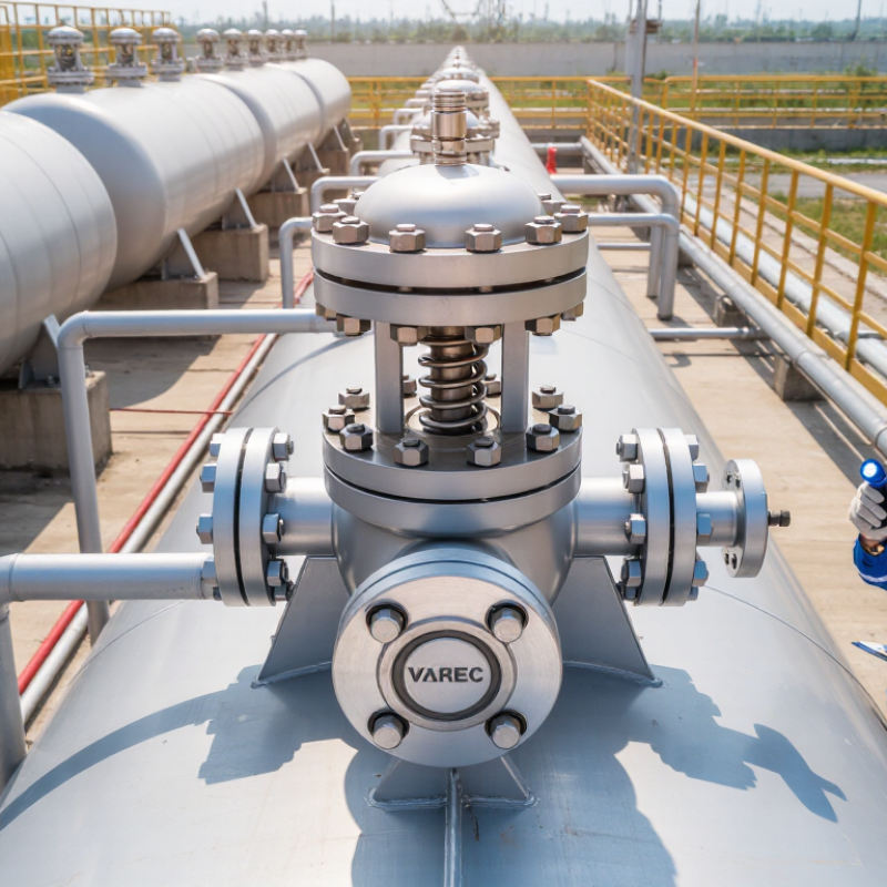
What Is the Best Varec Pressure Vacuum Relief Valve? The answer starts with tank service, not a product catalogue. API Standard 2000 bases venting needs on liquid movement, thermal breathing, and emergency exposure conditions. A tank receiving 100 m³ of liquid per hour needs that transfer rate assessed as a vapor-outflow case, alongside other operating conditions. The number is an input, not a valve size. Actual capacity depends on tank conditions and the applicable calculation method.
Set pressure must suit the tank’s documented pressure and vacuum limits. Do not choose a generic percentage without checking the tank design basis and API 2000 criteria. For normal venting, review filling, withdrawal, temperature swings, and vapor properties. For emergency venting, assess the applicable fire-exposure case. The U.S. EPA’s AP-42, Chapter 7.1, treats factors such as liquid throughput, vapor pressure, and temperature as relevant to storage-tank emissions estimates. Those same service details deserve careful review when defining the venting basis, though emissions calculations do not replace API 2000 sizing.
Easy to overlook. A solvent tank and a water tank can behave differently, even at similar transfer rates. Confirm the stored liquid, operating temperature, tank limits, and whether a flame arrester or piping adds resistance. Then compare required capacity with certified valve performance at the selected settings. One assumption may still be weak: actual operating data are often incomplete. Record that uncertainty, and verify it before final selection.
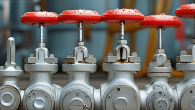
Choosing the best pressure-vacuum relief valve starts with matching its setpoints to the tank’s operating limits. Compare each model’s pressure setpoint, vacuum setpoint, and rated flow capacity. The pressure setting should protect the tank without venting during normal filling or temperature changes. The vacuum setting matters during pump-out and cooling, when a tank can pull inward. Small differences count.
Check the materials against the actual vapor, liquid, and outdoor conditions. Body metals, seat materials, and seals may respond differently to corrosive vapors, moisture, or heat. Review the technical data sheet and confirm the valve’s capacity at the expected flow—not just its connection size. A neat comparison table helps, but it can hide important differences in test conditions.
Tips: Write down normal operating pressure, maximum inflow, pump-out rate, and temperature range before comparing models. Confirm setpoint tolerances and material compatibility with the supplier. Real service conditions can be messier than the specification sheet suggests.
A practical shortlist should show pressure and vacuum settings beside materials and capacity. Then check whether each choice leaves enough margin below the tank’s allowable limits. Avoid assuming that a lower setpoint is always safer; frequent opening can cause product loss or unstable operation. If process data is incomplete, pause and verify it. That extra check may feel inconvenient, but guessing at vacuum demand is a poor trade.
The best pressure-vacuum relief valve is the one that meets the tank’s calculated loads at its actual set pressures. API Standard 2000 separates normal inbreathing and outbreathing from emergency venting. Normal loads include liquid transfer and temperature changes. Emergency demand can rise sharply during external fire exposure. API 2000 and ISO 28300 base these assessments on factors such as tank geometry, wetted area, operating conditions, and venting pressure. They do not make nominal pipe size a substitute for verified capacity.
Check the manufacturer’s certified flow data at the specified pressure and vacuum settings. Compare those rates with calculated normal and emergency loads, using consistent units such as standard cubic feet per hour or cubic metres per hour. A valve that handles routine filling may not provide enough emergency capacity. Sometimes a separate emergency vent is needed. One detail is easy to miss: flame screens, piping, and weather hoods can add pressure loss and reduce available flow. Include the actual installation in the review. API 2000 and ISO 28300 provide the engineering basis; the project’s tank data determine the required numbers. Recheck assumptions about liquid rate and fire exposure. Small errors matter.
Match each vent’s rated capacity to the tank’s normal and emergency venting loads.
This illustrative example compares required loads with selected capacities on the same stated air-flow basis. API 2000 venting requirements depend on the tank and its operating conditions; determine actual loads and verify certified capacity curves at the applicable pressure or vacuum settings before selecting equipment.
Choosing the best pressure vacuum relief valve begins with accurate unit conversion. A tank rated at 1 psi handles about 27.68 inches of water column. This difference matters during low-pressure storage applications. A setting of 6 in. H₂O equals approximately 0.217 psi. A setting of 10 in. H₂O equals roughly 0.361 psi. These values appear small, but they can protect a tank from deformation.
Field experience shows that unit confusion causes avoidable mistakes. I have seen drawings list psi while test gauges display inches of water. That mismatch can delay commissioning. It can also create an incorrect set pressure. Always confirm whether the rating describes pressure, vacuum, or both. Check the gauge range, calibration date, temperature, and fluid conditions. Small details matter.
The valve should match tank design pressure, operating cycles, and vapor flow requirements. A technical review should compare set points with normal breathing losses. The valve must open before unsafe pressure develops. It should also reseat reliably after relief. Do not rely on a catalog number alone. Installation position, piping resistance, and contamination can affect performance. My earlier assumption was that conversion solved everything. It does not. A practical selection combines verified calculations, inspection records, and site-specific operating experience.
The best Varec pressure vacuum relief valve depends on tank duty, not catalog popularity. Start with capacity. API Standard 2000 recommends evaluating normal outbreathing, liquid movement, thermal effects, and emergency conditions. EPA AP-42 Chapter 7 also identifies vapor pressure, working volume, and weather as key tank-breathing factors. A valve sized only from pump flow may fail during rapid filling or a hot afternoon.
Measure the real service. Record maximum filling and withdrawal rates, operating temperature, vapor composition, and required pressure and vacuum settings. Check wetted materials against corrosive vapors, oxygen exposure, and condensation. Compatibility is often underestimated. A seal that performs well in clean hydrocarbon service may harden quickly in contaminated vapor. ISO 28300 provides useful guidance for venting atmospheric and low-pressure storage tanks.
Maintenance needs should shape the selection. Choose a design that allows safe access, clear inspection, and simple replacement of seats, pallets, and gaskets. The U.S. EPA’s Leak Detection and Repair data show why small sealing defects matter: facilities track component leaks because repeated releases increase emissions and maintenance costs. Keep that reality in view. A lighter valve may look efficient, but sticky internals can create expensive downtime. I have seen specifications focus heavily on set pressure and barely mention inspection access. That is a mistake worth reconsidering.
| Valve Configuration | Recommended Service | Typical Pressure Setting Range | Typical Vacuum Setting Range | Nominal Flow Capacity | Common Connection Sizes | Suitable Materials | Maintenance Profile | Best-Fit Selection Reason |
|---|---|---|---|---|---|---|---|---|
| Low-Pressure Storage Tank Valve | Fixed-roof tanks storing diesel, fuel oil, water, or low-volatility liquids | +2 to +20 in. w.c. (5 to 50 mbar) | −0.5 to −2 in. w.c. (−1.2 to −5 mbar) | Approximately 500 to 20,000 Nm³/h, depending on size and set point | 2 to 12 in. flanged or threaded connections | Carbon steel body; stainless steel wetted or trim parts when corrosion requires | Low; inspect seats, guides, weights, and weather protection during scheduled tank inspections | Best general-purpose choice when the tank operates at low pressure and moderate breathing rates |
| High-Capacity Tank Breather Valve | Large atmospheric tanks with high filling, emptying, or thermal-breathing rates | +2 to +16 in. w.c. (5 to 40 mbar) | −0.5 to −1.5 in. w.c. (−1.2 to −3.7 mbar) | Approximately 10,000 to 100,000 Nm³/h | 8 to 24 in. flanged connections | Carbon steel, stainless steel, aluminum, or coated components selected for the stored vapor | Moderate; large discs and seats require lifting, alignment, and clearance checks | Most suitable when capacity and low pressure drop are more important than compact size |
| Corrosion-Resistant Vapor Valve | Acidic, saline, chemically active, or moisture-laden vapor service | +2 to +12 in. w.c. (5 to 30 mbar) | −0.5 to −1.5 in. w.c. (−1.2 to −3.7 mbar) | Approximately 1,000 to 30,000 Nm³/h | 2 to 16 in. flanged connections | 316 stainless steel or compatible alloy trim; gasket and coating selection is service-specific | Moderate to high; inspect corrosion, deposits, elastomers, and seat condition more frequently | Best when material compatibility and long-term sealing are the primary concerns |
| Flame-Arresting Tank Breather Assembly | Flammable liquid tanks requiring vapor-pressure and flame-propagation control | +2 to +12 in. w.c. (5 to 30 mbar) | −0.5 to −1.5 in. w.c. (−1.2 to −3.7 mbar) | Approximately 500 to 25,000 Nm³/h, subject to flame-arrestor pressure drop | 2 to 12 in. flanged connections | Carbon steel or stainless steel body with metallic flame-element assembly | High; flame elements must be inspected and cleaned to prevent blockage and excess pressure drop | Preferred where fire-risk control is required, provided the added pressure drop is acceptable |
| Pilot-Assisted Pressure Vacuum Valve | Applications requiring tighter control, higher set pressures, or reduced leakage | +8 to +40 in. w.c. (20 to 100 mbar) | −1 to −6 in. w.c. (−2.5 to −15 mbar) | Approximately 1,000 to 80,000 Nm³/h | 4 to 24 in. flanged connections | Carbon steel or stainless steel pressure body with chemically compatible pilot components | High; pilot passages, sensing lines, filters, and control components need regular testing | Best for demanding pressure-control requirements where a conventional weighted valve is insufficient |
| Insulated or Heated Service Valve | Wax-forming, crystallizing, or high-viscosity products that can obstruct moving parts | +2 to +20 in. w.c. (5 to 50 mbar) | −0.5 to −2 in. w.c. (−1.2 to −5 mbar) | Approximately 500 to 30,000 Nm³/h | 2 to 16 in. flanged connections | Carbon steel or stainless steel with insulation, heat tracing, and compatible seals | Moderate to high; verify heat-tracing continuity, insulation condition, and unrestricted disc movement | Best when temperature control is necessary to prevent sticking, freezing, or product buildup |