Leave Your Message
Choosing the right Flame Arrester starts with understanding what the equipment must protect and how the process actually operates. A unit suited to one vapor may not safely handle another. Gas composition, pressure, temperature, and flow rate all influence selection. So does the expected flame behavior. Small details matter.
Before comparing products, identify whether the installation is end-of-line or in-line. Then assess whether a deflagration or detonation hazard is credible, and review the distance between the potential ignition source and the arrester. These conditions affect the required design and testing basis. Check that the selected device has suitable performance data for the specific gas group and operating limits. A datasheet alone may not tell the whole story; installation drawings and the manufacturer’s technical guidance can clarify important constraints.
Practical experience helps reveal issues that calculations may miss. A cramped pipe layout, a likely source of fouling, or limited access for inspection can affect real-world reliability. Maintenance matters. Flame arresters need inspection and servicing according to their design and the process environment. There is no universal model that fits every line, and selection can involve trade-offs between protection, pressure drop, and maintainability. Even experienced teams can overlook an assumption. Recheck the operating conditions, confirm compatibility with connected equipment, and consult qualified engineering support when the hazard or installation is uncertain. This guide outlines the key questions to ask before choosing a Flame Arrester, helping readers make a more informed, verifiable decision.
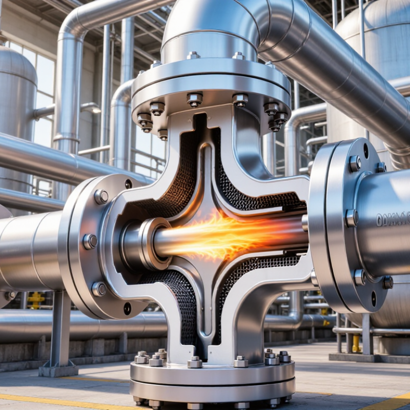
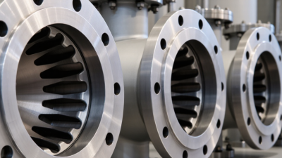
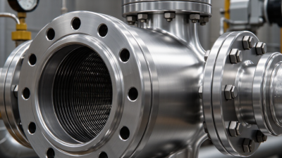
A flame arrester is a safety device fitted to a vent or process pipe to stop a flame travelling through a flammable gas or vapor mixture. Inside, a metal element creates many narrow passages. As flame enters these passages, the element absorbs heat and cools the flame below the temperature needed to keep burning. The flame is quenched. The device does not remove fuel or oxygen, and it is not a substitute for pressure-relief protection.
Performance depends on the gas, operating conditions, and flame behavior. ISO 16852:2016 sets test and performance requirements for flame arresters, including limits relevant to their intended use. A device suitable for a vent may not suit an in-line installation, where flow and flame conditions differ. The U.S. Chemical Safety Board’s 2006 Combustible Dust Hazard Study recorded 281 dust fires and explosions, 119 deaths, and 718 injuries. Those events involved a different hazard, but they underline an important boundary: gas flame arresters are not dust-explosion protection. I would not treat the device name alone as proof of protection.
Tips: Check the gas composition, pressure, temperature, flow, and installation location against the arrester’s tested limits. Keep the element clean and inspect it for blockage or damage. Small details matter. Have a qualified process-safety professional confirm the selection; actual piping conditions can be less tidy than drawings suggest.
| Selection Factor | What to Check | Why It Matters |
|---|---|---|
| Purpose and operating principle | A flame arrester allows gas or vapor to pass through narrow passages while dissipating heat from a flame front. The passages are designed to cool the flame below the temperature needed to sustain combustion. | Understanding the device’s function helps distinguish flame arresters from pressure-relief devices. A flame arrester is not, by itself, a substitute for pressure protection. |
| Gas or vapor composition | Identify the combustible substances and relevant mixture conditions. Check the applicable gas group and the arrester’s certified compatibility; for many gases, the Maximum Experimental Safe Gap (MESG) is used in gas-group classification. | Flame transmission characteristics vary by gas. A device suitable for one gas group may not be suitable for another. |
| Flame propagation scenario | Determine whether the hazard involves a deflagration (a subsonic flame) or a detonation (a flame coupled with a shock wave), and whether the flame can accelerate in the pipework. | Deflagration and detonation arresters are designed and tested for different conditions. Select a type specifically certified for the expected scenario and installation. |
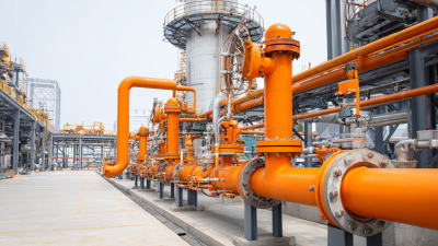
| Installation location | Choose between an end-of-line arrangement, fitted at an outlet to atmosphere, and an in-line arrangement, installed within a pipe or process connection. Confirm flow direction and any permitted mounting orientation. | Location affects the flame path, operating conditions, and applicable test limits. Follow the manufacturer’s installation instructions and certified use limits. |
| Pressure, temperature, and flow | Check normal and maximum operating pressure, temperature, gas flow rate, and allowable pressure drop. Include relevant start-up, shutdown, and upset conditions. | These conditions affect both safe performance and process operation. The selected unit must remain within its documented limits while providing the required flow. |
| Pipework and system layout | Review pipe diameter, connection type, distance from potential ignition sources, bends, valves, and other features that could affect flame acceleration or flow. | System geometry can influence the flame conditions reaching an arrester. Selection should account for the actual installation, not just the nominal pipe size. |
| Certification and standards | Verify that the arrester has appropriate test documentation and certification for the gas group, flame type, operating conditions, and installation. ISO 16852 is an international standard addressing flame arresters, including performance requirements and test methods. | Certification defines the conditions under which the device was evaluated. Confirm that the proposed application falls within those conditions and applicable local requirements. |
| Maintenance and fouling | Consider whether deposits, corrosion, liquids, or particulates could obstruct the element. Check inspection access, cleaning requirements, and the recommended maintenance interval. | Obstruction can increase pressure drop and may affect performance. Use an inspection and maintenance plan appropriate to the process and the device instructions. |
| Final selection check | Match the process data and hazard assessment to the arrester’s documented limits; have the complete installation reviewed by a qualified process-safety professional. | Correct selection depends on the combined gas, operating conditions, flame scenario, and system layout—not on device type or size alone. |