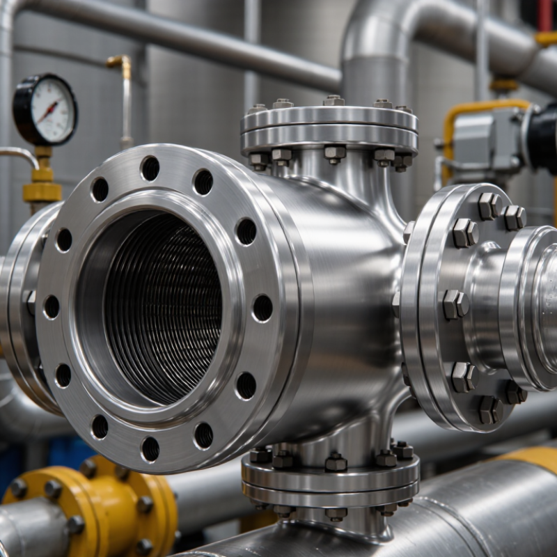
Choosing the 2026 Best Inline Flame Arrestor requires more than comparing prices or catalog photographs. Global buyers must examine gas composition, operating temperature, pressure, flow velocity, and possible flame travel. The correct Inline Flame Arrestor should match the process hazard and installation design. It should also carry suitable test evidence, material information, and maintenance guidance. A stainless-steel unit may look dependable, yet its performance can change when corrosive vapor, condensation, or dust enters the system.
Flame-arrester specialist Michael G. Pehr has expressed a useful principle: “Selection begins with understanding the hazard, not choosing a catalog size.” This idea remains practical for engineers and procurement teams. A detonation arrestor is not automatically suitable for every pipe section. End-of-line and in-line applications also require different technical checks. Buyers should review certified performance data, pressure-drop curves, connection standards, and inspection access before approving a supplier.
Real operating conditions matter. A unit installed near a tank may face heat cycles, vibration, and frequent cleaning. A remote gas line may demand stronger corrosion resistance and clearer service records. Some product pages provide impressive claims but limited test details. That should invite careful questions, not quick confidence. This guide compares leading options for 2026, while recognizing one uncomfortable truth: product selection is never perfect without accurate process data. Reliable decisions come from qualified engineering review, documented testing, and realistic maintenance planning. Safety depends on the whole system.
2026 Best Inline Flame Arrestor for Global Buyers?
What Is an Inline Flame Arrestor and How Does It Work?
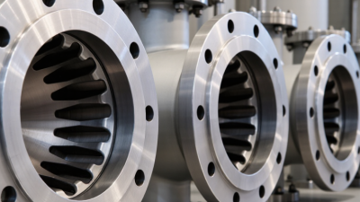
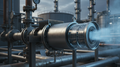
An inline flame arrestor is a passive safety device installed inside a gas or vapor pipeline. It helps stop flames from traveling through the line toward tanks, process equipment, or connected vessels. The device usually contains a metal element with many narrow passages. These passages allow gases to flow, but they restrict flame movement.
When a flame enters the arrestor, the flame front contacts the cooler metal surface. Heat transfers away from the flame and lowers its temperature below the ignition point. The passages are carefully sized to prevent the flame from crossing to the protected side. This process does not remove combustible vapor. It only interrupts flame propagation under defined conditions.
Selection requires more than matching pipe size. Engineers should check gas composition, operating pressure, temperature, flow rate, installation direction, and expected flame type. Deflagration and detonation services may require different designs. Certification and test data should match the actual application, not a similar one. A common mistake is treating an arrestor like a pressure relief device; it is not. Maintenance also matters, because dust, corrosion, or condensed liquid can block the element and increase pressure loss. Field conditions are rarely perfect. No selection chart can replace a careful hazard review and inspection plan.
2026 Best Inline Flame Arrestor for Global Buyers?
Key Types of Inline Flame Arrestors for Different Applications
Inline flame arrestors are not one universal product. Deflagration arrestors suit short, low-pressure vapor lines where flame speed remains limited. Detonation arrestors handle shock waves and higher flame velocity, making them more suitable for long pipelines, compressors, and storage connections. End-of-line models protect tank vents, while in-line models protect connected equipment during normal flow.
The correct choice depends on gas group, maximum experimental safe gap, pressure, temperature, and installation distance. ISO 16852 defines testing principles for flame arrestors, including endurance burning and explosion transmission. NFPA 30:2024 also stresses compatible equipment, bonding, and controlled vapor handling. These standards support engineering decisions, but they do not replace a site-specific hazard study. A neat specification can still be wrong. Pipe geometry, fouling, and condensate may change performance.
Tips: Confirm the gas composition, not only its trade name. Check pressure loss at actual flow. Ask for certified test data and maintenance intervals. Inspect mesh elements after contamination or overheating. The U.S. Chemical Safety Board’s incident investigations repeatedly show that weak hazard analysis and poor maintenance can turn small deviations into major events. That lesson is easy to underestimate. Local codes and qualified engineers should verify the final selection.
Selecting an inline flame arrestor starts with the process, not the product catalog. Record the vapor composition, operating pressure, temperature, flow direction, and pipe diameter. The arrestor must match the actual gas group and maximum experimental safe gap. ISO 16852 requires testing for specific flame types, including deflagration and detonation. A general-purpose unit may fail when conditions change.
Check pressure loss at normal and peak flow. Small pressure losses can reduce compressor efficiency and affect tank breathing. For maintenance planning, consider removable elements, inspection access, corrosion resistance, and drain arrangements. The 2024 NFPA 30 edition emphasizes controlling flammable-liquid vapor hazards through equipment design, separation, and ignition prevention. These controls work together. The arrestor is not a complete safety system.
Incident data deserves attention. The U.S. Chemical Safety Board reported 15 deaths and 180 injuries after the 2005 refinery explosion in Texas. That investigation showed how vapor release, ignition, and weak process controls can combine quickly. Selectors should review the full hazard study, not only the arrestor certificate. Ask for independent test documentation under ISO 16852, verified materials, and a clear installation manual. I would also question unusually low-cost units. Sometimes the missing detail is the real cost. Conditions can be misread, especially during seasonal temperature changes. Recheck the specification before ordering.
For global buyers, an inline flame arrestor is not selected by pipe size alone. ISO 16852 defines testing methods, performance limits, and application boundaries for flame arresters. Buyers should verify deflagration or detonation protection, gas group, maximum experimental safe gap, pressure rating, and installation distance. API 2000 also supports venting decisions for atmospheric and low-pressure storage systems.
Material selection depends on exposure. Stainless steel, especially 316L, suits humid or corrosive process areas. Carbon steel can reduce cost in dry, compatible service. The internal element still needs careful review. Crimped metal ribbon, sintered media, and perforated structures can produce different pressure drops and cleaning demands. Ask for certified flow curves, endurance-burning results, and maximum operating temperature. A passing laboratory test is not automatically suitable for a long, dusty pipeline.
The U.S. Chemical Safety Board reported 281 fatalities, 718 injuries, and 50 combustible-dust incidents from 1980 to 2005. That historical data still matters when buyers assess ignition risks. EN and IEC-related equipment requirements may also apply in hazardous locations, depending on the installation country. I would not treat a certificate as the complete answer. Real performance can change with deposits, condensation, vibration, and poor drainage. Inspection access is essential. So is a documented maintenance interval.
| Evaluation Dimension | Global Requirement or Typical Data | Relevant Standard or Engineering Basis | Buyer Verification Point |
|---|---|---|---|
| Primary function | Stops or limits flame transmission through a pipeline while allowing vapor or gas flow. | ISO 16852:2016 defines performance and testing principles for flame arresters. | Confirm that the device is a tested flame arrester, not only a mesh filter, strainer, or pressure-relief device. |
| Installation type | Inline units are installed within a pipe or process line; end-of-line units are mounted at a vent or outlet. | ISO 16852 distinguishes installation and flame-propagation configurations. | Select an inline configuration when the protected equipment and possible ignition source are connected by piping. |
| Flame-propagation mode | Deflagration arresters are used for subsonic flame propagation; detonation arresters are required where flame acceleration and shock waves may occur. | ISO 16852 test classifications include deflagration and detonation performance. | Do not substitute a deflagration arrester for a detonation arrester without documented application approval. |
| Pipeline geometry | Straight pipe runs, bends, reducers, tees, valves, and equipment volume can influence flame acceleration and pressure. | The tested installation arrangement should represent the actual piping configuration. | Provide pipe length, internal diameter, fittings, orientation, and distance to the potential ignition source. |
| Nominal size | Common process-line sizes range approximately from DN25 to DN600, subject to the certified product design. | Size selection is governed by flow capacity, connection standard, and certified test configuration. | Match the arrester bore to the pipe inside diameter and avoid an undersized unit that creates excessive pressure loss. |
| Connection standard | Flanged, threaded, wafer, and welded connections are available depending on size, pressure, and service. | Typical flange systems include ASME B16.5, ASME B16.47, EN 1092-1, and equivalent national standards. | Specify flange pressure class or PN rating, facing type, bolt pattern, and material compatibility. |
| Pressure rating | The allowable working pressure is design-specific; many atmospheric or low-pressure vapor systems use low-pressure service, while process systems may require substantially higher ratings. | Pressure design should follow the applicable piping, vessel, and flange code. | Compare maximum allowable working pressure, design pressure, vacuum rating, and pressure-transient resistance. |
| Operating temperature | Typical metal flame-arrester services may cover approximately −20 °C to +200 °C, but the certified range depends on the element, seals, housing, and gas mixture. | Temperature limits must be established by design calculations and test documentation. | Check continuous temperature, maximum excursion temperature, low-temperature impact requirements, and seal limitations. |
| Gas or vapor group | Hydrocarbon vapors, solvents, hydrogen-containing mixtures, and other flammable gases have different flame speeds and quenching requirements. | ISO 16852 testing uses defined gas mixtures; hazardous-area classification may also reference IEC 60079-20-1. | Identify the exact gas composition, concentration range, maximum experimental safe gap, and limiting oxygen concentration where relevant. |
| Hydrogen service | Hydrogen has high diffusivity and a broad flammability range, requiring specifically suitable testing and a low-temperature quenching element. | Use documented hydrogen or equivalent high-risk-gas test data; do not rely only on hydrocarbon test results. | Request the tested gas, flame mode, pressure, temperature, and installation arrangement for hydrogen applications. |
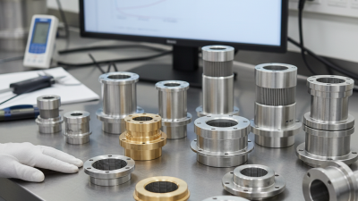
| Flame arrester element | Usually a crimped metal ribbon, perforated plate, sintered element, or other engineered quenching structure. | The element must provide sufficient heat absorption and narrow passages to quench the flame front. | Check element construction, removable design, inspection method, replacement availability, and certified orientation. |
| Housing material | Common options include carbon steel, 304 stainless steel, and 316/316L stainless steel. | Material selection should consider pressure, corrosion, temperature, and process-fluid compatibility. | Use 316/316L where chloride exposure, marine atmosphere, or aggressive chemical service makes 304 unsuitable. |
| Element material | Stainless steel is widely used for corrosion resistance and dimensional stability; nickel alloys may be selected for severe chemical or high-temperature service. | The element material must retain mechanical integrity and heat-transfer performance at the specified temperature. | Confirm material grade, weldability, corrosion allowance, and compatibility with cleaning chemicals. |
| Pressure drop | Pressure loss increases with gas velocity, fouling, smaller passages, and reduced free area. The actual value must come from the supplier’s flow curve. | Hydraulic sizing should use the actual gas molecular weight, temperature, pressure, flow rate, and compressibility. | Require clean and fouled pressure-drop data at minimum, normal, and maximum flow conditions. |
| Flow capacity | Capacity is application-specific and should be stated as mass flow, standard volumetric flow, or actual volumetric flow with reference conditions. | Flow data must correspond to the same gas, pressure, temperature, and arrester orientation as the intended service. | Avoid comparing flow ratings that use different reference conditions or different allowable pressure drops. |
| Maximum operating pressure | Must be greater than the normal operating pressure and credible pressure excursions, while remaining within the housing and connection design limits. | Pressure protection remains necessary; a flame arrester is not a substitute for a relief valve or rupture-disc system. | Review pressure-relief scenarios, blocked outlet cases, explosion pressure, and vacuum conditions separately. |
| Monitoring and maintenance | Fouling can increase pressure drop and reduce effective flow area; inspection intervals depend on service cleanliness and risk. | Inspection and maintenance should follow the manufacturer’s instructions and the site’s process-safety management system. | Consider differential-pressure gauges, removable elements, drain provisions, cleaning access, and spare-element strategy. |
| Hazardous-area suitability | The arrester assembly may require suitable electrical accessories, bonding, grounding, and area-classification compliance. | IEC 60079 series requirements may apply to electrical equipment and instrumentation installed in explosive atmospheres. | Verify equipment group, zone or division, gas group, temperature class, grounding continuity, and certification scope. |
| Explosion-pressure resistance | A flame arrester may limit flame transmission but does not necessarily withstand every explosion pressure or deflagration-to-detonation transition. | System design may also require explosion venting, suppression, isolation, or pressure-resistant equipment. | Obtain the tested pressure rating and integrate the unit into a documented explosion-protection assessment. |
| International conformity | Global projects commonly request ISO 16852 test evidence plus applicable regional pressure, piping, and hazardous-area documentation. | Potential references include ISO 16852, EN standards adopting ISO requirements, ASME piping rules, and IEC 60079 requirements where applicable. | Request certificates, test reports, material certificates, drawings, pressure calculations, and a declaration of conformity. |
| Best selection profile for global buyers | A certified inline detonation or deflagration arrester matched to the actual gas, piping geometry, flow, pressure, temperature, and corrosion environment. | Performance should be demonstrated by application-relevant testing rather than by nominal size or material grade alone. | Prioritize tested performance, complete documentation, maintainability, verified flow data, and local code acceptance. |
2026 Best Inline Flame Arrestor for Global Buyers?
Installation, Inspection, Maintenance, and Replacement Guidelines
Choosing the best inline flame arrestor starts with process data, not price. Confirm the gas group, operating temperature, pressure, flow direction, and pipe size. Check the arrestor’s certified performance range. Local codes and site permits may add requirements. A qualified engineer should review the design before installation.
Install the unit with the marked flow arrow facing the process direction. Keep nearby pipework properly supported and avoid unnecessary bends. Remove shipping covers, dirt, and moisture before connection. Use compatible gaskets and tighten fasteners evenly. Do not paint over vents, labels, or inspection points. Small installation errors can reduce protection.
Inspection should follow the risk assessment and operating schedule. Look for corrosion, dents, loose bolts, blocked passages, and damaged seals. Record pressure drop and compare it with the normal baseline. A sudden increase may indicate fouling. Isolate and depressurize the line before opening any component. Never clean flame-control elements with tools that can deform them. Use approved methods and trained personnel.
Maintenance records should include dates, findings, measurements, and replaced parts. In practice, teams sometimes postpone inspection when production is busy. That choice needs reconsideration. Replace the arrestor after severe corrosion, mechanical damage, failed testing, or an unapproved process change. Replacement also becomes necessary when certification no longer matches the service. Confirm the new unit’s dimensions, rating, and connection type before removal. A careful fit check prevents an expensive second shutdown.