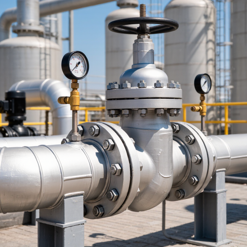
Choosing a Pressure Relief Valve is a safety decision, not a routine purchasing task. The right valve must respond before pressure threatens people, equipment, or production. A small mismatch can create serious consequences. Consider the fluid, normal operating pressure, temperature, required relieving capacity, and discharge conditions. These details belong together.
Trevor Kletz, a respected process-safety authority, warned, “If you think safety is expensive, try ignorance.” His words remain relevant when engineers select a Pressure Relief Valve from a catalog. The valve’s set pressure should protect the weakest pressure-containing component. Its certified capacity must match the credible overpressure scenario. Backpressure, corrosion, viscosity, and two-phase flow may also change performance. A valve that looks suitable on paper may behave differently beside a hot pump or a long discharge pipe.
Experience matters here. Inspect the installation space, confirm the inlet and outlet sizes, and review the maintenance history. Ask whether the valve can be tested without creating an unsafe condition. Check the manufacturer’s documentation, certification, materials, and operating limits. Independent review is wise for critical systems. Still, no checklist replaces engineering judgment. That is the uncomfortable part. Process conditions change, and old assumptions may remain unnoticed for years. This guide explains how to compare valve types, calculate requirements, verify standards, and avoid common selection mistakes. It does not replace a qualified process engineer’s review. A careful choice protects more than equipment. It protects the people standing nearby.
How to Choose a Pressure Relief Valve?
A pressure relief valve is a safety device that protects equipment from excessive pressure. It opens automatically when system pressure reaches a defined set point. The valve then releases fluid until pressure returns to a safer level. It is commonly installed on boilers, storage vessels, compressors, and process piping.
Why is it needed? Pressure can rise unexpectedly when an outlet becomes blocked, a control system fails, or trapped liquid expands during heating. External fire exposure can create another serious risk. Without a suitable relief path, a vessel may deform, rupture, or release hazardous material. That result is rarely caused by one failure alone. Small design assumptions can combine quickly.
Choosing the valve requires more than matching a pipe size. Confirm the operating pressure, set pressure, fluid type, temperature, required discharge capacity, and backpressure. Check whether the fluid contains solids or causes corrosion. A valve that works well with clean steam may perform poorly with sticky liquid. The discharge line also needs careful routing, support, and safe termination. It should not create dangerous spray, noise, or reaction forces.
Maintenance findings often reveal a practical problem: a correctly selected valve can still fail if it is isolated, fouled, or tested irregularly. A qualified engineer should verify the design against applicable technical standards and site conditions. Inspect the nameplate, seals, and set-pressure records. Do not guess here. A few minutes of review may prevent a very expensive mistake.
A pressure relief valve automatically releases excess pressure when it reaches a defined set pressure. Selecting the correct valve requires checking the fluid, operating temperature, set pressure, required capacity, back pressure, materials, and applicable safety codes.
Design reference: Normal operating pressure is commonly kept below the valve set pressure to reduce nuisance lifting and allow stable operation. The percentages shown are typical engineering guidelines and must be verified against the applicable code, process conditions, and valve manufacturer requirements.
How to Choose a Pressure Relief Valve?
Which Pressure Relief Valve Type Fits the Application?
Choosing the valve type starts with the process, not the pipe size. A spring-loaded valve suits many clean, stable systems with moderate backpressure. It reacts directly to pressure changes and is relatively simple to maintain. I have seen maintenance teams prefer this design when access is limited and quick testing matters.
Pilot-operated valves can handle high flow rates and tight pressure control. They work well on large vessels, gas systems, and applications with steady operating conditions. However, dirty fluid may block small pilot passages. Filtration and regular inspection become essential. Small details matter.
A balanced bellows valve may be better when backpressure could affect set pressure. It also helps protect the spring from corrosive process media. For liquid service, confirm that the valve can manage flashing, thermal expansion, and required discharge capacity. Vacuum relief devices may be necessary when a tank cools or drains quickly.
Check the set pressure, accumulation limits, temperature range, fluid phase, and discharge piping. Local codes and certified sizing methods should guide the final selection. A calculation based only on normal operation is incomplete. Unexpected shutdowns, blocked outlets, and fire exposure can change the required capacity. I have also found that installation assumptions are often wrong. Review actual backpressure, maintenance access, and lifting points before approval. A valve that fits on paper may be difficult to test in the field.
Determining the pressure setting starts with the equipment’s maximum allowable working pressure (MAWP). The valve set pressure should not exceed that limit. Check the applicable design code and local requirements before final approval. Normal operating pressure also matters. A practical margin helps prevent simmering, leakage, and repeated lifting. Do not guess.
Next, define the worst credible relieving scenario. Consider blocked outlets, fire exposure, control failure, thermal expansion, and unexpected gas generation. Record the fluid, temperature, molecular weight, viscosity, and required relieving rate. These details directly affect the valve capacity and orifice area. A neat calculation can still be wrong if the scenario is incomplete.
Valve size depends on required flow, inlet pressure loss, built-up backpressure, and discharge piping resistance. Select the smallest certified valve that safely handles the calculated load, but avoid treating pipe size as valve capacity. Use recognized sizing methods and verified manufacturer data. Field reviews often find undersized discharge lines, poor drainage, or unrecorded backpressure. Small details matter. Recheck the calculation after process changes, especially when operating pressure, fluid composition, or equipment volume changes. A qualified engineer should review the final selection and confirm inspection, testing, and installation requirements.
A pressure relief valve should match the process, not just the pressure rating. Start by checking the fluid, operating temperature, concentration, and possible contaminants. A valve exposed to wet chlorine chemistry needs different materials from one handling clean compressed air. Stainless steel may resist corrosion well, while carbon steel can suit dry, non-corrosive service. The choice is rarely obvious.
Pay close attention to the body, spring, seat, disc, and seals. Each part contacts a different environment. Seal materials must remain flexible at low temperatures and stable at high temperatures. Some metals can gall during repeated operation. Others may become brittle after long exposure to heat or chemicals. Material compatibility charts help, but they cannot replace process-specific engineering review.
Performance features deserve equal attention. Confirm the set pressure, relieving capacity, blowdown, and allowable back pressure. A valve may open correctly in a test room yet perform differently in a vibrating plant line. I have found that inlet piping losses are often underestimated. That mistake can affect actual capacity. Look for documented testing, calibrated instruments, traceable materials, and clear maintenance intervals. Field inspection should verify corrosion, leaks, spring condition, and discharge routing. A useful specification also states the operating range, not only the maximum pressure. Small details matter.
| Evaluation Dimension | Typical Option or Requirement | Suitable Service Conditions | Key Performance Considerations | Selection Guidance |
|---|---|---|---|---|
| Valve Body Material | Carbon Steel | General industrial service, water, steam, air, and many non-corrosive hydrocarbons | High mechanical strength and relatively low cost; vulnerable to corrosion in wet, acidic, or chloride-rich environments | Use protective coatings or corrosion allowances where appropriate, and confirm compatibility with the process fluid |
| Valve Body Material | Stainless Steel | Moisture, mildly corrosive media, food-processing service, and many chemical applications | Better general corrosion resistance than carbon steel; austenitic grades may be susceptible to chloride stress corrosion cracking under certain conditions | Select the stainless-steel grade according to chloride concentration, temperature, acidity, and required cleanliness |
| Valve Body Material | Nickel Alloy | Strongly corrosive, high-temperature, or chemically aggressive process environments | Excellent resistance to many acids, alkalis, and high-temperature degradation mechanisms; higher material and fabrication cost | Choose only after reviewing the exact chemical composition, concentration, temperature, and exposure time |
| Valve Body Material | Bronze or Copper Alloy | Water, air, low-to-moderate temperature utilities, and selected marine or plumbing applications | Good resistance in many water services and good machinability; may be unsuitable for ammonia, certain acids, and high-pressure or high-temperature duty | Verify pressure, temperature, dezincification, galvanic-corrosion, and fluid-compatibility requirements |
| Trim and Spring Material | Stainless Steel Trim with Corrosion-Resistant Spring | Wet, humid, outdoor, and mildly corrosive environments | Improves resistance to corrosion, sticking, and loss of spring performance compared with unprotected carbon-steel components | Confirm that the spring alloy retains its mechanical properties throughout the full operating-temperature range |
| Seat Material | Metal Seat | High-temperature service, steam, fire exposure, erosive fluids, and applications requiring high mechanical durability | Strong resistance to temperature and wear; normally permits a small amount of leakage compared with a soft seat | Use when temperature, fire safety, or particle erosion is more important than the lowest possible leakage |
| Seat Material | Soft Seat, such as PTFE or Elastomer | Clean gases, liquids, and moderate-temperature services requiring tight shutoff | Provides lower leakage and improved sealing; temperature, chemical compatibility, aging, and decompression limits must be checked | Verify the material's maximum temperature, pressure, chemical compatibility, and resistance to extrusion |
| Set Pressure | Defined Opening Pressure | All pressure-containing systems | The valve should open at or below the allowable accumulation permitted by the applicable design code | Set pressure must be coordinated with the equipment design pressure, operating pressure, and applicable regulations |
| Operating Pressure Margin | Stable Difference Between Operating and Set Pressure | Systems with fluctuating or continuous operating pressure | Insufficient margin can cause simmering, chatter, leakage, or premature wear | Follow the valve manufacturer's and governing code's recommended operating-to-set-pressure relationship |
| Relieving Capacity | Required Mass or Volumetric Flow Rate | Fire exposure, blocked outlet, thermal expansion, control-valve failure, and other credible overpressure scenarios | Capacity depends on fluid phase, molecular weight, temperature, pressure, discharge coefficient, and back pressure | Calculate the largest credible relief load and size the valve using a recognized engineering standard |
| Fluid Phase | Gas, Steam, Liquid, or Two-Phase Flow | Different process and utility systems | Gas and steam sizing differs substantially from liquid sizing; two-phase flow can require specialized analysis | Identify the phase at relieving conditions rather than relying only on normal operating conditions |
| Back Pressure | Built-Up and Superimposed Back Pressure | Valves connected to headers, scrubbers, flare systems, or long discharge piping | Back pressure can alter set pressure, capacity, stability, and required valve type | Consider a balanced bellows or pilot-operated design when conventional spring-loaded performance is inadequate |
| Discharge Coefficient | Certified Flow-Performance Parameter | Relief-capacity calculations | Represents the effective flow capability of the valve and is used in recognized sizing equations | Use certified values applicable to the exact valve design, fluid phase, and sizing standard |
| Temperature Range | Minimum, Normal, and Relieving Temperature | Ambient service, cryogenic service, steam, hot oil, and high-temperature process systems | Temperature affects body strength, spring performance, seat leakage, fluid properties, and material compatibility | Check pressure-temperature ratings and the operating limits of every wetted and non-wetted component |
| Leakage Performance | Allowable Seat Leakage Class | Systems handling toxic, flammable, expensive, or environmentally sensitive fluids | Lower leakage may require soft seats, better surface finishes, precise alignment, and stricter testing | Specify the required leakage acceptance criteria and test procedure before purchasing |
| Valve Configuration | Conventional Spring-Loaded, Balanced Bellows, or Pilot-Operated | Different back-pressure, capacity, contamination, and stability conditions | Conventional designs are simple; balanced designs reduce back-pressure effects; pilot-operated designs can offer high capacity and tighter operation but require cleaner service | Match the configuration to back pressure, fluid cleanliness, maintenance capability, and required response stability |
| Connection Size and Rating | Inlet and Outlet Size with Pressure Class | Integration with vessels, piping, and discharge systems | Undersized inlet piping can restrict capacity; excessive pressure loss may cause instability or unacceptable inlet pressure drop | Check flange or thread standards, pressure-temperature ratings, inlet pressure loss, and discharge-piping reaction forces |
| Discharge Arrangement | Open Discharge or Closed Piping System | Non-hazardous utilities versus toxic, flammable, corrosive, or environmentally controlled fluids | Closed discharge systems require evaluation of back pressure, drainage, condensation, reaction forces, and safe routing | Route discharge to a safe location and prevent liquid accumulation or blockage in the relief path |
| Standards and Certification | Applicable Pressure-Relief and Inspection Requirements | Pressure vessels, boilers, pipelines, chemical plants, and regulated installations | Standards define design, sizing, testing, marking, inspection, and documentation requirements | Identify the governing jurisdiction and applicable standards before selecting the valve design |
| Maintenance and Testing | Inspection Interval, Testability, and Spare Parts | Critical or continuously operating systems | Contamination, corrosion, deposits, and spring fatigue can impair performance over time | Choose a design that supports planned inspection, bench testing, cleaning, and replacement of wear components |
| Documentation | Capacity, Materials, Set Pressure, Test, and Traceability Records | Safety-critical and regulated applications | Complete records support installation verification, future maintenance, audits, and incident investigation | Require certified drawings, material information, test reports, sizing calculations, and calibration records |
Choosing a pressure relief valve starts with the installation environment. Confirm the set pressure, temperature range, fluid compatibility, discharge capacity, and connection size. ASME Section VIII requires sizing against credible overpressure scenarios, not normal operating pressure. Installation records should show the calculation, calibration certificate, orientation, and discharge routing. A valve may be correctly selected yet poorly installed. Misaligned piping, blocked outlets, or excessive back pressure can defeat its purpose.
Testing must reflect actual service conditions. API 576 recommends visual inspection, operational checks, bench testing, and documented results. The National Board’s accident summaries repeatedly identify weak inspection practices and uncontrolled pressure as recurring contributors to equipment incidents. Maintenance intervals should follow service severity, manufacturer guidance, and site history. Corrosive fluids, vibration, polymer buildup, and frequent lifting may require shorter intervals. A fixed annual schedule is convenient, but it can be wrong. Review failed-test trends, leakage records, and process changes after every inspection cycle.
Tips: Photograph the valve before removal. Record tag number, set pressure, test pressure, and test medium. Check whether the isolation valve is locked open. Ask one uncomfortable question: could the discharge line freeze, flood, or become obstructed? Have a qualified inspector witness testing. Keep certificates with the equipment history, not in a separate folder. Never treat a passed bench test as proof of field readiness.